What is a Fiber Optic Sensor?

Fiber Optic Sensor is a type of non-contact detection and measurement device. It operates using optical principles, detecting objects by measuring the intensity of light that strikes the target and reflects back to the sensor. It excels at detecting small objects, is ideal for installation in tight spaces with limited clearance, and performs exceptionally well in high-risk environmental conditions.
This type of sensor consists of two main components:
1. Fiber Amplifier: Its primary function is to emit light into the fiber optic cable and process the signals for object detection. Other features vary depending on the specific model.
2. Fiber Unit: Essential for transmitting light from the amplifier to the target object. Fiber units are available in various shapes and configurations to suit different applications and installation requirements.
How Does a Fiber Optic Sensor Work?
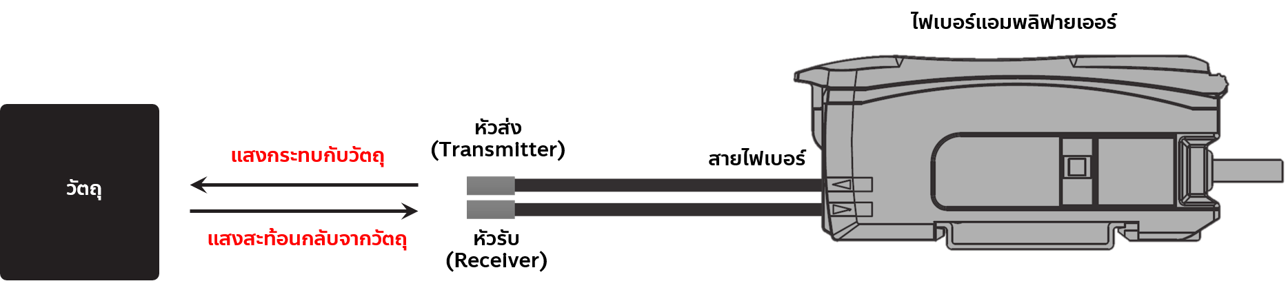
Operation diagram of a Fiber Optic Sensor
The operation begins when the internal circuitry of the fiber amplifier generates and emits light. This light travels through the fiber optic cable to the transmitter head, strikes the object, reflects back to the receiver head, and is sent back to the amplifier. The amplifier then processes the returned light intensity into a numerical value. Users can configure a Threshold value, allowing the amplifier to trigger an output signal whenever the reflected light intensity rises above or falls below the designated threshold.
Classification by Sensing Mode (4 Main Types):
1. Through-Beam Type (Emitter-Receiver)
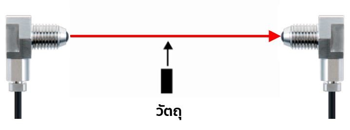
Through-Beam type sensor diagram
The light beam is transmitted from the emitter head directly to the receiver head. Under normal operating conditions, the receiver constantly receives the light signal. This setup detects objects moving through the beam path; when an object passes between them, it blocks the light. When the light fails to reach the receiver, the internal circuit registers the interruption, changing the output state of the receiver.
2. Retro-Reflective Type (With Reflector)
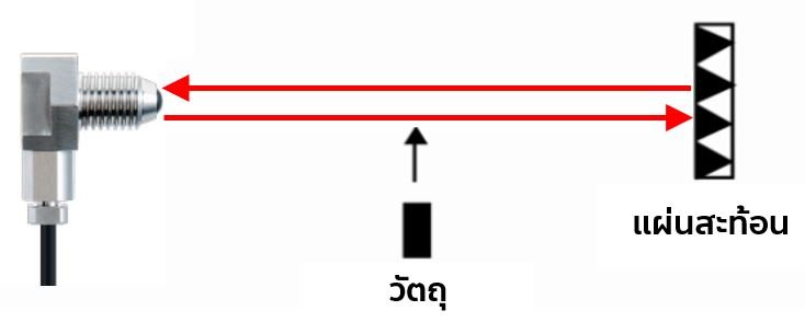
Retro-Reflective type sensor diagram
Both the transmitter and receiver are housed within a single fiber head, used in tandem with a reflector. It detects objects crossing the beam path. When an object passes in front of the sensor, it blocks the light beam traveling to the reflector, preventing the receiver from detecting the returned light. This interruption registers within the internal circuitry, altering the output state of the receiver.
3. Diffuse-Reflective Type (Direct Reflection off Object)
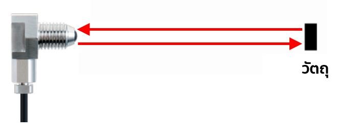
Diffuse-Reflective type sensor diagram
This mode utilizes direct reflection off the target object, housing both the transmitter and receiver inside a single fiber head, similar to the retro-reflective type. It detects objects passing directly in front of the sensor face. The passing object reflects the emitted light beam back into the receiver. Upon receiving this reflected light, the internal circuit registers the presence of the object and changes the receiver's output state.
4. Limit-Reflective Type (Limited Distance Reflection)
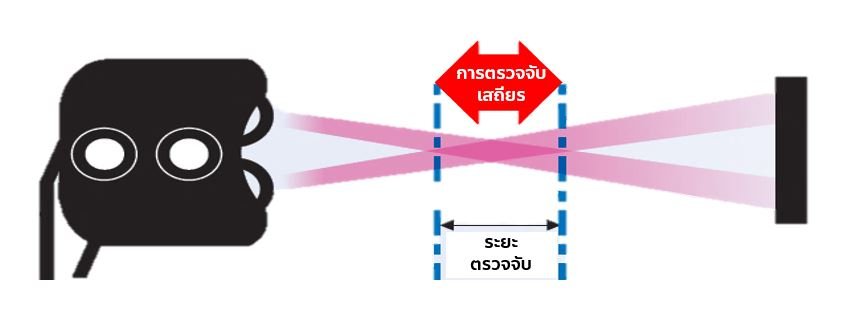
Limit-Reflective type sensor diagram
Like the diffuse type, this mode uses direct reflection off the object with a combined transmitter and receiver head. However, it is designed to detect objects moving within a strictly limited distance range. Objects passing within this specific sensing range reflect the light back to the receiver, causing the internal circuit to detect them and change the output state. This configuration significantly reduces false detections caused by background elements and is highly effective for precise positioning applications.
Advantages of Fiber Optic Sensors
- Compact fiber optic head sizes make them ideal for confined spaces and small object detection.
- Suitable for operations in hazardous or high-risk environments.
- Wide variety of configurations available to suit diverse application needs.
- Superior capability in detecting subtle differences in contrast or target variance compared to standard photoelectric sensors.
Based on the comprehensive information provided above, we hope you now have a solid understanding of the fundamentals of Fiber Optic Sensors to help you choose the right model for your application. If you are interested in purchasing or require more product details, please feel free to contact us via Line at @IAMALL, email at support@iamall.co.th, or by phone at 02-743-8988.


