Things to Know About Temperature Controller

Types of Temperature Controller
They can be broadly classified into two major categories: Analog Controllers and Digital Controllers.
1. Analog Temperature Controller
This is a type of temperature controller used for regulation where the internal circuitry does not utilize a microcontroller. Instead, it relies strictly on analog electronic circuits, or in some cases, features no electronic circuitry at all, using just two different metals that act as a switch. This type of controller is less commonly used today, both in industrial fields and applications requiring high measurement and control accuracy, as it has been largely replaced by digital controllers which offer far superior precision.
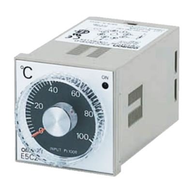
Analog Temperature Controller
2. Digital Temperature Controller
This is the most widely used type of temperature controller today. It functions to regulate temperature with high accuracy and can manage heating, cooling, or both heating and cooling simultaneously. It offers versatile functionality and can be integrated with modern control networks, such as Industry 4.0 systems, for data logging or remote control via communication ports like RS-485 or MODBUS. The fundamental components of a digital controller include a PV (Process Variable) temperature display screen, an SV (Set Point Variable) setting section, signal input channels, and signal output channels.
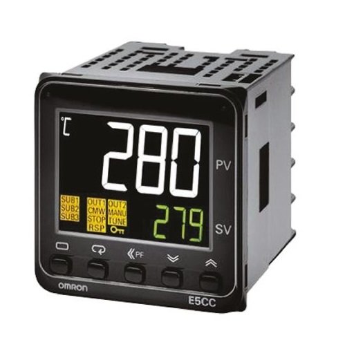
Digital Temperature Controller
Key Variables of a Temperature Controller
- PV (Process Variable) is the actual temperature value measured in real-time.
- SV (Set Point Variable) is the target temperature value that the user wants the system to maintain steadily.
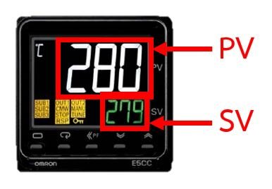
Diagram showing Temperature Controller variables
Working Principle of a Temperature Controller
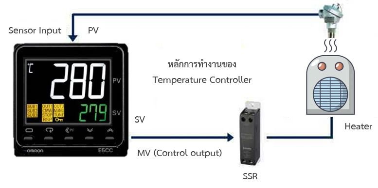
Diagram showing the working principle of a Temperature Controller
The operation of a temperature controller begins by configuring the SV setting, which identifies the desired control temperature for the production process (for example, setting it to 500°C). After that, the controller continuously compares or calculates the difference between the PV and SV values. The PV value is acquired by reading the input sensor. If the PV value is lower than the SV value, the controller will command the Control Signal Output to send a signal through an SSR (Solid State Relay), which acts like a switch, to power the heater and increase the temperature. When the PV temperature exceeds the SV, it reduces the Control Signal Output to lower the heater's operation. This control loop process represents a fundamental regulation method known as On-Off Control.
Input Types
- Thermocouples: Types J, K, N, T, R, and others. Each type features a different temperature measurement range. Type K is the most popular due to its exceptionally wide measurement range. Thermocouples are ideal for applications involving extreme high or low temperatures.
RTDs (such as PT100): RTDs provide higher linearity, high precision, and offer the best long-term operating stability. - DC Voltage: 1-5 V, 0-5 V, 0-10 V, 0-10 mV
- DC Current: 4-20 mA, 0-20 mA
- Infrared: These are non-contact temperature sensors that utilize infrared light to measure temperature instead of physical contact. This type of sensor is perfect for applications where a standard sensor cannot be directly mounted to the workpiece, such as moving components or rollers. Examples include OMRON's infrared sensor models ES1B and ES1A.
Output Types
- Relays: Featuring SPDT or SPST contacts, these are used with magnetic contactors. This is the most popular type of output due to its ease of use, durability, and high current-carrying capacity.
- Voltage Pulse: 12 VDC, 24 VDC used with SSRs. Solid State Relays offer much faster switching speeds and more stable operation than magnetic contactors. This output type is widely used in applications requiring a high switching frequency and is simple to wire because it does not require an external power supply like a relay output.
- Current/Linear: Options include 4-20 mA, 0-20 mA, 0-10 VDC, and 0-5 VDC. This type of output can be connected to a wide variety of compatible control devices, depending on the application design. For heating applications, it is typically paired with an SCR (Power Controller) that accepts 4-20 mA, 0-20 mA, 0-10 VDC, or 0-5 VDC inputs. SCRs can handle much higher heater power loads compared to SSRs.
Temperature Control
Temperature control refers to the process of regulating the temperature within a targeted system to match a configured set value.Control Systems
1. Open-Loop Control System or Sequence ControlThis is a control configuration where actions are executed sequentially or based on pre-set time intervals, such as traffic signal switching or setting timer schedules for air conditioners. This type of control does not monitor or consider the actual output result of the process; it simply drives the system according to a fixed sequence of steps.

Diagram of an Open-Loop Control System
2. Closed-Loop Control System or Feedback Control
This is a control mechanism that continuously monitors and evaluates the actual output result of the process. It measures the variable and feeds it back to be compared against the target set value. The controller then switches or modulates the output to bring the measured value in line with the set value. This principle represents standard automatic control systems, widely used for temperature regulation, water level control, and motor speed control.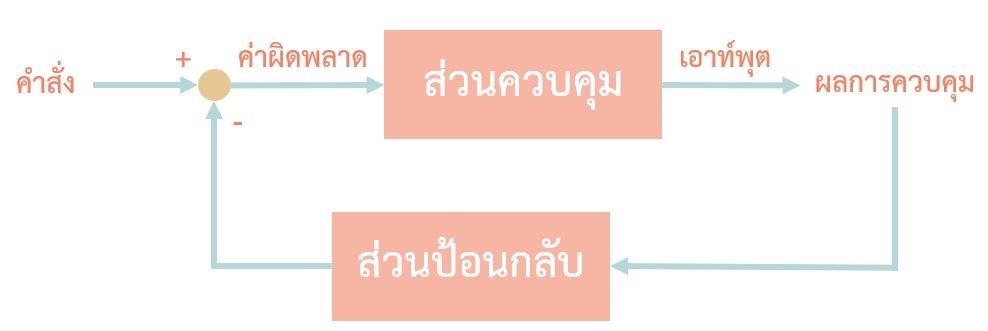
Diagram of a Closed-Loop Control System
Basic Methods Used for Temperature Control
1. ON/OFF Control
This is a two-position control method: either fully on or fully off. The output switches cleanly between 0% and 100%. The output shuts down only when the temperature reaches the set point.
In ON/OFF control, both the opening and closing of the output occur directly around the setpoint. For instance, if the setpoint is 100°C, the output cuts off at 100°C and turns back on immediately when the temperature drops below 100°C. If a physical contact relay output is used, high-frequency switching can rapidly degrade the contacts or cause them to arc and weld together. Hysteresis is a setting used to determine how much the temperature must drop below the setpoint before the output turns back on (in a heating application). For example, if the setpoint is 100°C and Hysteresis is set to 5°C, the output turns off at 100°C and turns back on at 95°C. This cycle repeats continuously, causing the temperature under ON/OFF control to fluctuate or swing (Hunting) around the setpoint, generating an Overshoot every time control initiates.
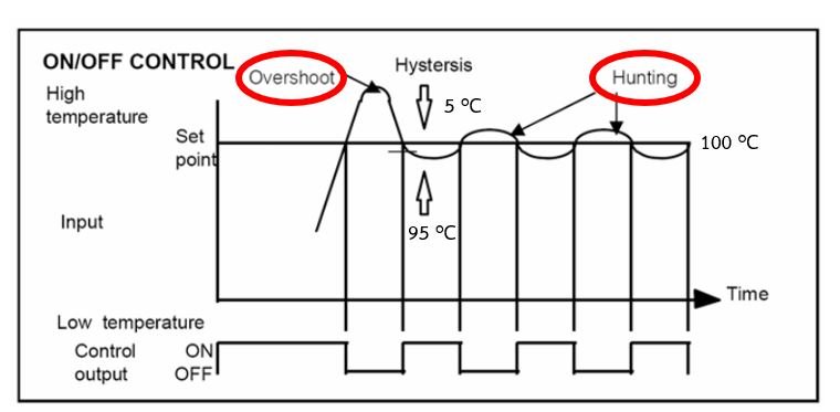
Graph of ON/OFF Control
- Overshoot refers to the temperature peaking past the setpoint value during initial startup, due to external system disturbances, or following a change in the setpoint value.
- Hunting refers to the temperature oscillating up and down in synchronization with the cyclic switching of the output, typically swinging around the configured setpoint.
2. PID Control
PID control helps maximize process control efficiency. Within this framework, Proportional (P) action reduces Overshoot and Hunting, Integral (I) action eliminates Offset (the steady-state difference that can persist between the setpoint and the measured value), and Derivative (D) action responds quickly to external system disturbances. To implement PID control, the P, I, and D parameters must be configured.
Fortunately, OMRON temperature controllers feature an Auto-Tuning function that automatically calculates and applies the ideal PID values based on the surrounding environment. PID control significantly minimizes overshoot; while an ON/OFF controller cuts off exactly when PV reaches SV, a PID controller modulates or turns off power before reaching the SV. This throttle window is dynamically calculated according to the external environment learned during Auto-Tuning.
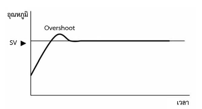
Graph of PID Control
Temperature Controller Functions
- Auto-tuning is an automated function that calculates optimal PID parameters by learning from environmental temperatures and analyzing external impacts on the system. It determines the most effective PID values to bring the system temperature to the SV quickly and with peak efficiency.
- Self-tuning functions to automatically recalculate and adjust the PID values whenever process changes occur during live operations.
- Heater Burnout Alarm is a specialized safety feature that monitors heater performance. It reads the current passing through the heater; if the heater burns out or breaks, this function triggers an alarm output signal.


